IoT based Timer Switch using Blynk and NodeMCU with Notification Feature
In todays world we all are surrounded by many smart devices and gadgets. We can use them in solving many day to day problems. Also if you are bit electronics savvy then you can create you own customized IoT devices. IoT based Timer Switch using Blynk and NodeMCU with notification feature.
If you have any appliance or device which needs to be switched on daily for a particular interval of time then this device will help you to automate it. This will not only switch it on and off but also it will send you a status notification.
Today, we are going to build a IoT based Timer Switch using Blynk and NodeMCU which switches ON/OFF at times which we set in Blynk App. Let’s have a look on the components required to build this project.
Materials Required
For building this project you need below materials. These are easily available online. We have attached some affiliate links (Best Buy). If you purchase we will get some help to run this blog.
- ESP8266 NodeMCU Wifi Module x 1 (Best Buy)
- 2 channel relay Module x 1 (BEST BUY)
- Breadboard (Best Buy) Optional
- Jumper cables (Best Buy)
- 5v Power Supply
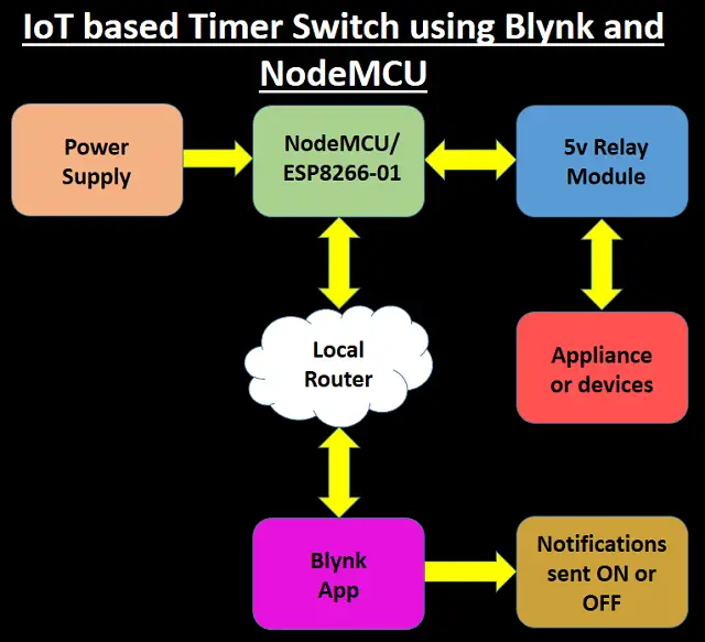
How this works?
Once you have setup the blynk project and you hardware, based on your time setting your devices will be turned ON and OFF. It will also send a status notification along with current status.
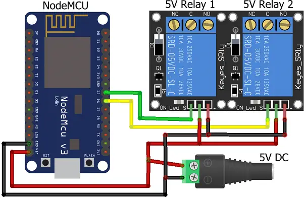
Circuit Diagram
You can build this project on a breadboard or you can directly connect it. The circuit diagram of the IoT based Timer Switch using Blynk and NodeMCU.
The circuit is powered by 5V power supply. The NodeMCU is used to communicate with Blynk server to send and receive the data. The 2 relay module will switch on/off the devices connected to it. Relays are connected to D5 and D6 pins of NodeMCU.
Must Read:
- Smart Switch using Blynk | IoT Based WiFi Switch
- Touch Based Switch board using TTP223
- PIR based Motion Switch | PIR Sensor Light
- IoT based Door Security Alarm Project with Blynk
Setting up a Blynk Project
Download the Blynk App from below links as per the platform you are using
Widgets and their uses
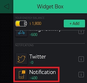
Notification Widget: This widget is used to send notifications as per the execution of action.
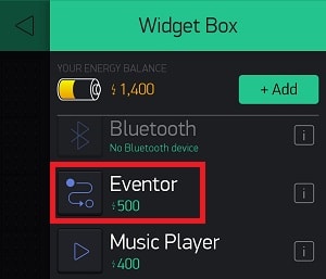
Eventor Widget: This widget is used to schedule event or actions. Here you have to mention date, time and day. Along with action need to be taken. This is a kind of scheduler.
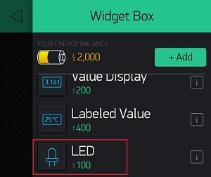
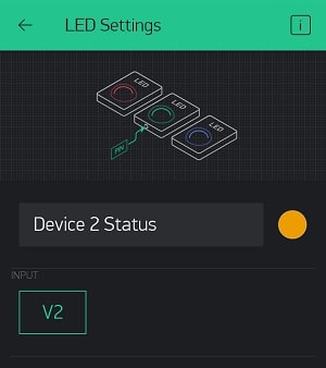
LED Widget: This is used to indicate the current status of devices i.e. switched on or off.
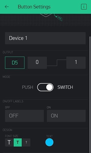
Button Widget: For switching the devices manually.
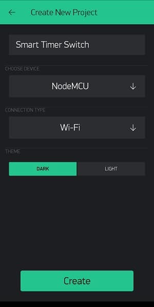
Now lets setup a Blynk project, Tap on New Project
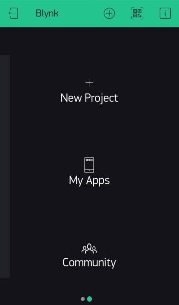
Enter the Name of the project as you like. Choose the Device NodeMCU. Tap on Create.
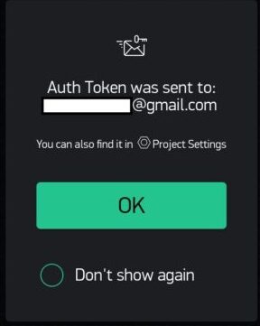
Auth token will be sent on your registered email address.
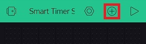
Tap on the highlighted icon below to get the widget list
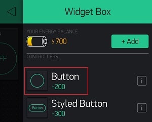
Select 2 Button widget. You can choose Styled Button as well
Now scroll down and select 2 LED widget
Now add a notification widget
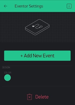
Tap on Eventor widget. This widget will work as a timer.
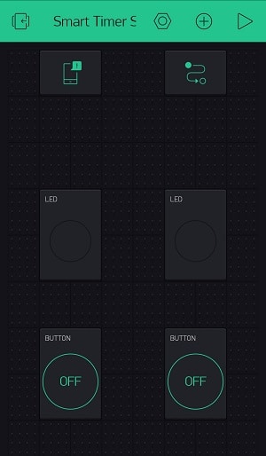
Now place the widgets properly by selecting and dragging them.
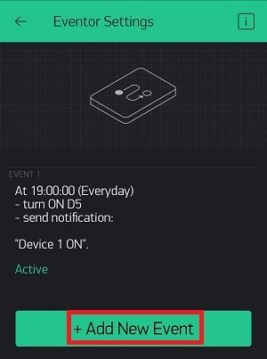
Now Tap on Eventor widget to configure it. Tap on ADD NEW EVENT
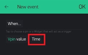
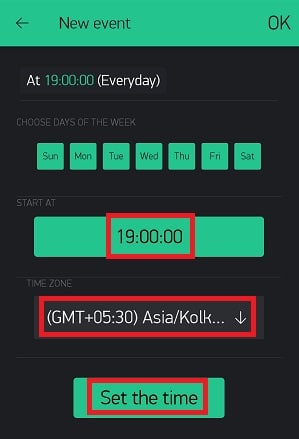
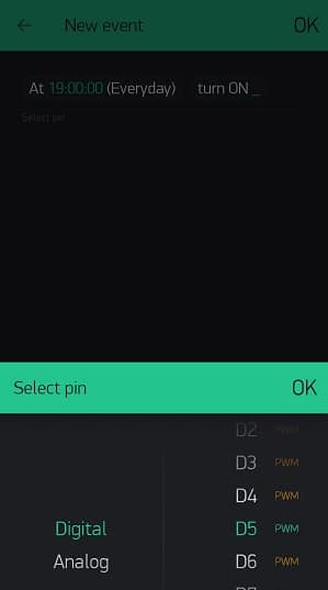
Tap on Time and select the time at which it will trigger.
The time is in 24Hrs format. You can select the time zone accordingly. Tap on Set the Time.
Now we are going to select the action. So here we will be turning on the pin. Tap on turn ON pin
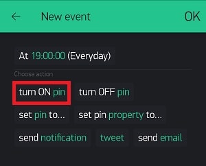
Select the pin. This refers to the pin connected to relay with NodeMCU.
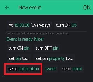
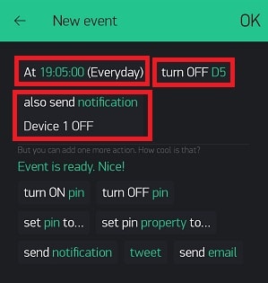
Now we will set send notification message. This message will trigger when a action is taken as per scheduled time.
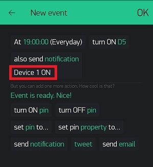
Here we have added a message Device 1 ON
We have added on event and in similar way we can add event to turn off the Device 1
Configure as shown below to turn off Device 1
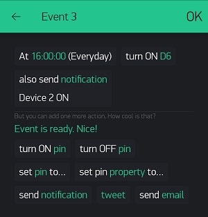
Similarly to turn on Device 2 configure as shown below
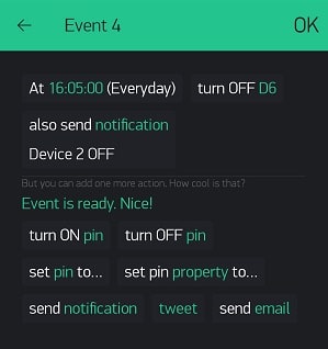
To turn off the Device 2 below are the configurations
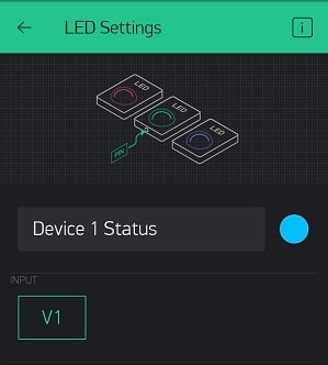
For LED widget select V1 as virtual pin
Virtual pin V2 is selected for second LED.
For buttons below are the configurations
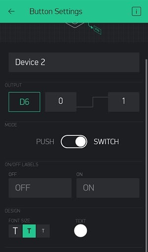
Similarly for Device 2 you can configure
Coding the NodeMCU
Before uploading the code, make sure you have pasted the Auth Token. Also make sure to update your WIFI network details. You can copy paste the code and put it into Arduino.
For uploading the code in NodeMCU please check the link below
Easy NodeMCU Programming with Simple Steps
#include <ESP8266WiFi.h>
#include <BlynkSimpleEsp8266.h>

const int relay_1 = 14; // Relay 1 Conneted with D5(GPIO 14) pin of NodeMCU
const int relay_2 = 12; // Relay 2 Conneted with D6(GPIO 12) pin of NodeMCU

char ssid[] = "WIFI_Name"; // Your WiFi credentials.
char pass[] = "WIFI_Password"; // Set password to "" for open networks.
char auth[] = "Auth Token"; // You should get Auth Token in the Blynk App.

WidgetLED led1(V1);
WidgetLED led2(V2);

SimpleTimer timer;

void buttonLedWidget()
{
if (digitalRead(relay_1) == HIGH)
{
led1.on();
}
else
{
led1.off();
}

if (digitalRead(relay_2) == HIGH)
{
led2.on();
}
else
{
led2.off();
}

}
void setup()
{
//Serial.begin(9600);
Blynk.begin(auth, ssid, pass);
pinMode(relay_1,OUTPUT);
pinMode(relay_2,OUTPUT);
timer.setInterval(500L, buttonLedWidget);
}

void loop()
{
Blynk.run();
timer.run(); // running timer every second
}
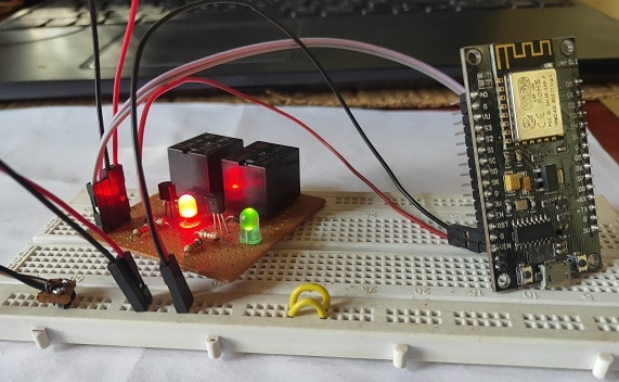
Construction and Testing
After connecting all the components and setting up the blynk project, its time to test the project. Once your hardware is connected with internet, it will also reflect in blynk app. Now you can use button widget to control 2 devices manually. You can also schedule repetitive task and get notified on switching on or off.
Conclusion
If you have something to be done regularly on a specific time then this project will help you automate. This project is also capable of sending notification while switching the devices. The blynk project also has blynk button for manually switching the devices. You can build this and comment on how this project is used in real-time.