Interfacing 16×2 LCD with Raspberry Pi
LCD is the most commonly used part when you are doing electronics projects with Raspberry pi. It will help you whenever you will want to display the data. So, in this post you are going to learn Interfacing 16×2 LCD with Raspberry Pi. We will use the 16X2 LCD to display the data on it. You may be wondering that what does this 16X2 means. This means that LCD has 16 columns and 2 rows. Other LCD’s with 16X1 and 16X4 displays are also available. Each character of LCD consists of 5X10 i.e. 50 pixels. These LCD’s are compatible with the Hitachi HD44780 driver which controls the pixels.
Components Required
The components you will be required for Raspberry pi LCD display interfacing are as follows
- Raspberry Pi
- LCD 16×2
- Potentiometer 4.7 KΩ
- Resistor 330 Ω
- Jumper cables
- I2C LCD Module
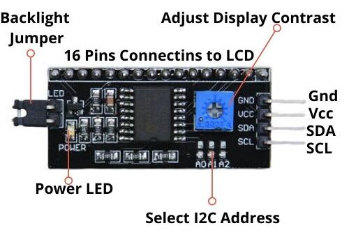
Pin out of Liquid Crystal Display
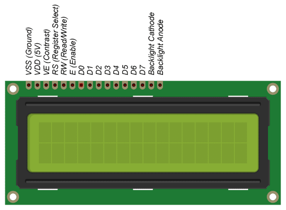
VSS: This is the ground pin.
VDD: This is the 5V pin.
V0: This pin controls the contrast of the LCD.
RS (Register Select Pin): This pin control where you are writing data in the LCD’s memory. There are two types of registers; Data register which holds what goes on the screen and the instruction register where the LCD looks for the next instruction.
R/W (Read/Write Pin): This pin selects the mode; Reading mode or Writing mode. Connecting it to ground will put the LCD in the read mode.
E (Enable Pin): This pin enables the writing to the registers.
Data Pins: There are 8 data pins (D0-D7). The high or low state of these pins represents the bits that you are writing to register in the write mode or the values you are reading in the read mode.
The last two pins are for the LCD back light. Some LCD’s have 16 pins and some have 14 pins. If you have a 14 pin LCD then it means that there is no back light.
A (LED+): This pin is the positive connection of the back light.
K (LED-): This pin is the negative connection of the back light.
Circuit Diagram and Connections

Source:- Raspberry Pi
The LCD can be connected with the Raspberry pi in both 4 bit as well as 8 bit mode. The 4 bit mode required 6 GPIO pins while the 8 bit mode requires 10 GPIO pins. Because the 4-bit mode requires less GPIO pins so we are going to use the 4-bit mode. Both modes have same speed.
16X2 LCD | Raspberry Pi |
VSS | GND |
VDD | 5V |
V0 | MIDDLE PIN OF 4.7K POT |
RS | GPIO26 |
R/W | GND |
E | GPIO19 |
D4 | GPIO13 |
D5 | GPIO6 |
D6 | GPIO5 |
D7 | GPIO21 |
A | TO 5V THROUGH 330 OHMS RESISTOR |
K | GND |
Installing the Library
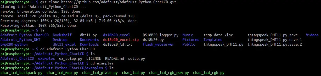
First of all, you will need to install the Adafruit library for LCD, so type the below command in the Raspberry pi terminal.
git clone https://github.com/adafruit/Adafruit_Python_CharLCD.git
Then enter into the directory we just created by typing the following command.
cd ./Adafruit_Python_CharLCD
Now run the setup by typing the below command.
sudo python setup.py install

sudo python3 setup.py install
Then go the examples folder and open file ‘char_lcd.py’ file. Change the pin numbers in that examples to the ones shown below.
Python Code to Print and Scroll Text on LCD
The below code will simply print and scroll the text on the LCD.
from Adafruit_CharLCD import Adafruit_CharLCD # Importing Adafruit library for LCD
from time import sleep # Importing sleep from time library to add delay in program
# initiate lcd and specify pins
lcd = Adafruit_CharLCD (rs=26, en=19, d4=13, d5=6, d6=5, d7=21, cols=16, lines=2)
lcd.clear()
# display text on LCD, \n = new line
lcd.message('WELCOME TO \nIoT STARTERS')
sleep(2)
# scroll text on display
try:
     while 1:
for x in range(0, 16):
lcd.move_left()
sleep(0.1)
sleep(1)
# scroll Right
for x in range(0, 16):
lcd.move_right()
sleep(0.1)
sleep(3)
# If Keyboard Interrupt command is pressed
except KeyboardInterrupt:
pass
# Clear the screen
lcd.clear()
Construction & Testing
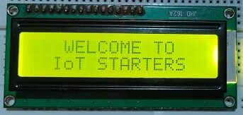
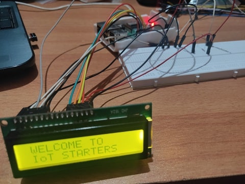
After executing the python code we can get the below output. This indicates the LCD is connected properly with raspberry pi and ready to display data.
Connecting the LCD using I2C Protocol
Now we will see how to connect a 16×2 LCD using I2C protocol with the Raspberry Pi.
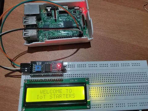
The backpack module uses the I-squared-C (or I2C) protocol to communicate with the Raspberry Pi, which uses only two wires: SDA and SCL (data and clock). LCD display requires 5V to power and display and it will be powered by Raspberry Pi. For sending the data to LCD from Raspberry Pi, I2C protocol will be used. It is safe to connect such display to the Raspberry Pi directly.
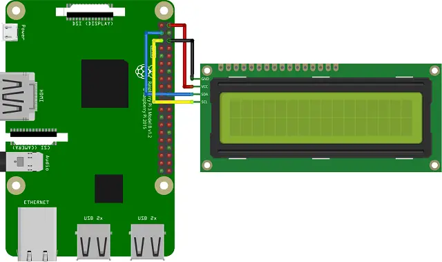
Connections
I suggest using wires of different colors to connect the LCD display. This minimizes the risk of damage due to incorrect connections. The connection has to be correct between LCD and Raspberry Pi.
Raspberry Pi | I2C LCD Module |
5V | VCC |
GND | GND |
Pin 3 (GPIO 2) | SDA |
Pin 5 (GPIO 3) | SLC |
Before you start using the I2C 16×2 LCD display with Python, you need to make sure that the I2C protocol is enabled on your Raspberry Pi. You can use below command to enable this protocol. Enabling I2C requires a reboot to completely enable it.
sudo raspi-config
After restarting the Raspberry Pi the I2C protocol will be enabled which will supports multiple devices connected to the same bus. It also identifies each device by their unique hardware address. It’s time to connect the display and see whether it is recognized. Double-check your wires before making the connection. The 27 hexadecimal addresses happen to be the most common, but if your display’s address is different then you need to change it. For example, it could be 3f. The I2C address depends on the chip version of the module. you can run the below command to find the I2C address.
sudo i2cdetect -y 1
The easiest way to program this 16×2 I2C LCD display in Python is by using a dedicated library. There are many to choose from. Install the library using this command
git clone https://github.com/the-raspberry-pi-guy/lcd.git
After installation execute below command
cd lcd/
Some examples are listed here. You can run the below command and check.
./demo_clock.py
To edit the below code use below command.
pi@raspberrypi:~/lcd $ sudo nano demo_clock.py
You can also copy the below code and and run it.
Code Analysis
You need an import and an LCD object instance.
import drivers
from time import sleep
from datetime import datetime
We are using below commands to display the text.
display.lcd_display_string(" WELCOME TO ", 1)
display.lcd_display_string(" IoT STARTERS ", 2)
Below command to clear the written text
display.lcd_clear()
I use the clear function at the end of the program, otherwise the message will stay on the display after the program ends. The two numbers (1 and 2) at the end of the text function indicate which line of the display to use.
lcd.text(“Hello,”, 1)
lcd.text(“Raspberry Pi!”, 2)
This is an opportunity to adjust the contrast, especially if the display does not show anything, if you don’t see the “Hello, Raspberry Pi!” message.
Suggested Reading:
- Weather Station with Raspberry Pi PICO and DHT11
- Controlling a servo motor using Raspberry Pi Pico
- Configuring BMP280 Sensor with Raspberry Pi
- Configuring Motion Sensor with Raspberry Pi Pico
- Weather Station with BMP280 Sensor and Raspberry Pi Pico
- IoT Pulse Oximeter Using NodeMCU MAX30100 & Blynk
- DIY Digital clock with RTC DS1307 and Raspberry Pi PICO
- IoT Security Camera using ESP32-Cam Blynk and PIR Sensor
- Reading built in Temperature sensor values of Raspberry Pi PICO
- How to send sensor data to Thingspeak using Raspberry Pi
- Raspberry Pi Flask Web Server with DHT11
- DHT11 Data Logger using Raspberry Pi and Python code
- IoT based Fire Security Alarm System using NodeMCU
- Raspberry Pi Temperature Logger DS18B20
- DHT11 Data Logger using Raspberry Pi and Python code
Python Code
It’s time to write a test program and check it.
With the rpi_lcd library the programming of the display is very easy just a couple of lines of code.
# Import necessary libraries for communication and display use
import drivers
from time import sleep
from datetime import datetime

# Load the driver and set it to "display"
# If you use something from the driver library use the "display." prefix first
display = drivers.Lcd()

try:
     print("Writing to display")
     display.lcd_display_string(" WELCOME TO ", 1) # Write line of text to first line of display
while True:
# Write line of text to Second line of display
         display.lcd_display_string(" IoT STARTERS ", 2)
except KeyboardInterrupt:
# If there is a KeyboardInterrupt (when you press ctrl+c), exit the program and cleanup
        print("Cleaning up!")
        display.lcd_clear()
Summary
In this tutorial we have learnt about interfacing a 16×2 LCD with Raspberry Pi. We have used both the methods to connect the the LCD with RPI. This is very useful in small projects. Last but not the least, don’t forget to share this article.
RaspberryPi 4B. Doesn’t work. Display lights up, Top row filled with squares, contrast works but that’s all. Running from Thonny. Thonny shows no errors.
Please check the connections and libraries
Hi, I am using the I2C Protocol on a RaspberryPi 3B+ and followed all your steps. However when I run the code on Thonny it complains that there is no module “drivers” even though when I open my folders I can locate the drivers folder. Could you assist? Thank you!